_
The PRIVATE and SECURE way to share
ONE BATHROOM between TWO ROOMS
The PRIVATE and SECURE way to share
ONE BATHROOM between TWO ROOMS
- Electrically lock your bathroom/ensuite from an adjacent occupant until usage is complete.
- Flexible plans suit both secure and non-secure access between adjacent rooms.
- Doors default to ‘Unlocked’ during power failure.
- Auxiliary contact will operate Lights & exhaust fan for two minutes after the room is vacated
- Alarm contact can be extended to a buzzer or remote system if a ‘locked’ door is breached.
SM108b Door Interlock System
GENERAL DESCRIPTION
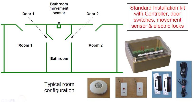
This system may be used to control electric door latches on a bathroom/ensuite that is shared between two apartments or rooms. It ensures ready access for each room occupant, while maintaining the privacy and security of a personal bathroom.
Access doors may be hinged or sliding or both, as electric door latches may be selected to suit different room layouts. All installations are intrinsically safe, operating from low voltage DC and Australian approved power supplies. During emergency events or mains power failures, any locked rooms will automatically unlock.
If the bathroom lighting and/or exhaust fan has been connected to the room controller, then the lights will be automatically activated whenever anyone enters the room. They will remain on as long as the room is occupied and will turn off Door lock a few minutes after the room is vacated.
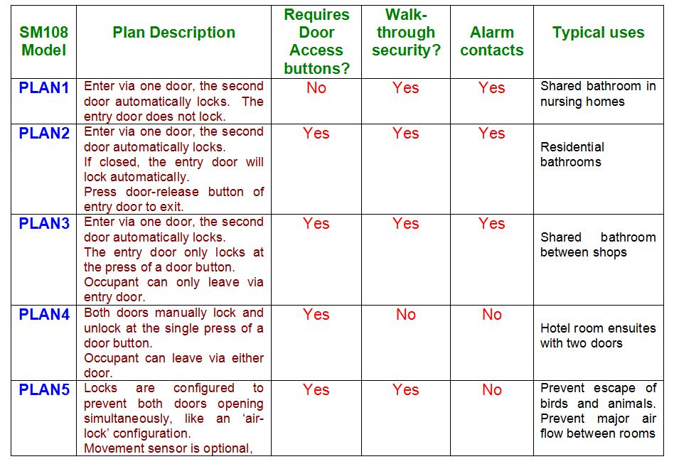
Five basic plans are available. This table provides a brief indication of the differences between each plan, so that the ideal one can be selected for a specific installation.
Depending upon the physical door layout and door frame materials at the site, there are four different latch types to choose from. These are the standard Hinged Door Latch (HDL), the Drop Pin Latch (DPL), the Flush Magnetic Latch (FML) and the Exposed Magnetic Latch (EML) (it is possible to mix latch types between doors for a given installation.)
SM108 INTRODUCTION VIDEO
This system may be used to control electric door latches on a bathroom/ensuite that is shared between two apartments or rooms. It ensures ready access for each room occupant, while maintaining the privacy and security of a personal bathroom.
Access doors may be hinged or sliding or both, as electric door latches may be selected to suit different room layouts. All installations are intrinsically safe, operating from low voltage DC and Australian approved power supplies. During emergency events or mains power failures, any locked rooms will automatically unlock.
If the bathroom lighting and/or exhaust fan has been connected to the room controller, then the lights will be automatically activated whenever anyone enters the room. They will remain on as long as the room is occupied and will turn off Door lock a few minutes after the room is vacated.
Five basic plans are available. This table provides a brief indication of the differences between each plan, so that the ideal one can be selected for a specific installation.
Depending upon the physical door layout and door frame materials at the site, there are four different latch types to choose from. These are the standard Hinged Door Latch (HDL), the Drop Pin Latch (DPL), the Flush Magnetic Latch (FML) and the Exposed Magnetic Latch (EML) (it is possible to mix latch types between doors for a given installation.)
SM108 INTRODUCTION VIDEO
FIVE PLANS OF OPERATION TO SUIT DIFFERENT CONDITIONS
A 3 MINUTE VIDEO CLIP SHOWING THE OPERATION OF PLAN 1
MORE DETAILS ON EACH PLAN ARE DESCRIBED IN THE DOWNLOADABLE MANUAL
Click on the link below for the current manual describing full details on operation and installation of the SM108 system. Current pricing for all system components is shown at the bottom of this page.
Also downloadable below are additional drawings of latch dimensions.
Click on the link below for the current manual describing full details on operation and installation of the SM108 system. Current pricing for all system components is shown at the bottom of this page.
Also downloadable below are additional drawings of latch dimensions.
| sm108b_version_10_manual.pdf |
| dpl_drop_latch_mechanical_drawing.pdf |
| latch_drawing.pdf |
| eml_exposed_magnetic_latch_mechanical_drawing.pdf |
FOUR LATCH TYPES AVAILABLE FOR SYSTEM KITS
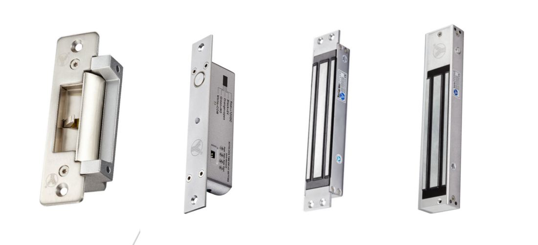
The image below (from left to right) shows the four basic latch types:
Note that all four types are identically priced
The image below (from left to right) shows the four basic latch types:
- Hinged Door Latch (HDL),
- Drop Pin Latch (DPL),
- Flush Magnetic Latch (FML)
- Exposed Magnetic Latch (EML)
Note that all four types are identically priced
DOOR SWITCH OPTIONS FOR FML AND EML LATCHES
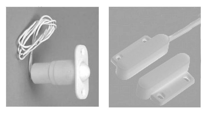
Note that the magnetic latches FML and EML require the fitting of an additional door sensing switch. (The Hinged Door and Drop Pin latches have integral switches and don't require this)
Two types of switch sensor are available. Recessed Ball Switch type (RBS) and Surface Mounted Switch type (SMS)
The appropriate switch type should be specified when ordering either of the magnetic latches.
Where sufficient space exists above the door, the Recessed Ball Switch is a good choice as it remains concealed when the door is closed. However, some door frames lack the space for this option and the Surface Mounted Switch is a better fit. Both styles perform the same electrical function.
Recessed Ball Switch type (RBS) Surface Mounted Switch type (SMS)
A TUTORIAL VIDEO ON FITTING A FLUSH MAGNETIC LATCH (FML) TO A SLIDING DOOR
This short clip describes the process of mounting the latch and latch-plate assembly to a common cavity slider door
This short clip describes the process of mounting the latch and latch-plate assembly to a common cavity slider door
A TUTORIAL ON FITTING A HINGED DOOR LATCH (HDL) TO A STEEL FRAME DOORWAY (9 minutes)
Where HDL latches are used, we have a template to assist in cutting out a hole in a metal frame.
The template is available for download as a pdf file (below)
Where HDL latches are used, we have a template to assist in cutting out a hole in a metal frame.
The template is available for download as a pdf file (below)
A PRINTABLE TEMPLATE FOR MOUNTING A HINGED DOOR LATCH IN A METAL DOOR FRAME
Note, check your pdf printer program to ensure correct scaling has been used. Under Print Scale, Select 'Default' rather than 'Fit to printable area'.
Cutout should be 124 mm high and 56 mm wide. Distance between centres of 6 mm drill holes is 148 mm
Note, check your pdf printer program to ensure correct scaling has been used. Under Print Scale, Select 'Default' rather than 'Fit to printable area'.
Cutout should be 124 mm high and 56 mm wide. Distance between centres of 6 mm drill holes is 148 mm
| sm108_hdl_cut_template.pdf |
ALTERNATIVE INSTALLATION METHOD
In some situations, such as laboratory rooms, a more basic form of interlock is all that is needed, where only one door may be used at a time. When any door is opened, all other doors have their latches energised and become locked. When all doors are closed, then all doors are unlocked. A simple circuit consisting of door latches and a 12V power supply is described within the viewable pdf file below. No control SM108 controller unit is required for this basic arrangement.
Click on the link below to download this simplified latch arrangement .
| simple_door_interlock_method..pdf |
_____________________________________________________________________________________________________________
PRICING INFORMATION
SM108b Door Interlock System, includes:
- 1 x SM108b unit,
- 1 x 12V power pack
- 2 x latches (specify HDL, DPL, EML or FML )
- 2 x Door Switches, where Magnetic Latches are selected (specify RBS or SMS)
- 1 x 360º movement sensor)
Qty 1-9 $542.00+
Qty 10+ $505.00+
SM108b Illuminated door Lock/unlock buttons (for plans 2,3,4)
Qty 1-9 $33.70+
Qty 10+ $29.00+
SM108 EMERG Emergency room access wall switch (for plans 2,3,4)
Qty 1-9 $33.70+
Qty 10+ $29.00+
SM108b Additional LATCHES purchased separately (12V, normally unlocked, becomes locked when energised )
Qty 1-9 $180.90+ ( specify HDL, DPL, EML or FML )
Qty 10+ $148.80+
(last updated April 2023)
_________________________________________________________________________________________________________________
PRICING INFORMATION
- Payment can be made to Alian Electronics via EFT or Pay Pal
- All prices in $AUD and do not include the cost of freight. (Click HERE to view the Freight Information page)
- When buying from within Australia add 10% GST
- (Overseas sales are GST Free, but depending upon local policy, you may need to pay tax/duty for goods to be released by your Customs)
- When buying from within Australia by Pay Pal, add 2.4% for Pay Pal transaction fee.
- When buying from Outside Australia by Pay Pal add 3.6% for Pay Pal transaction and currency conversion fee.
- (When buying from Outside Australia using Telegraphic Transfer ( TT ) the buyer will pay transaction fees with their bank.)
- Transaction details, Freight & other charges will be shown on a Proforma Invoice supplied to you before you pay.
SM108b Door Interlock System, includes:
- 1 x SM108b unit,
- 1 x 12V power pack
- 2 x latches (specify HDL, DPL, EML or FML )
- 2 x Door Switches, where Magnetic Latches are selected (specify RBS or SMS)
- 1 x 360º movement sensor)
Qty 1-9 $542.00+
Qty 10+ $505.00+
SM108b Illuminated door Lock/unlock buttons (for plans 2,3,4)
Qty 1-9 $33.70+
Qty 10+ $29.00+
SM108 EMERG Emergency room access wall switch (for plans 2,3,4)
Qty 1-9 $33.70+
Qty 10+ $29.00+
SM108b Additional LATCHES purchased separately (12V, normally unlocked, becomes locked when energised )
Qty 1-9 $180.90+ ( specify HDL, DPL, EML or FML )
Qty 10+ $148.80+
(last updated April 2023)
_________________________________________________________________________________________________________________